
This wideband radio frequency (RF) jammer simultaneously blocks all commercial FM broadcast band (87.5 MHz to 108 MHz) transmissions within the jammer's transmission range.
Disclaimer: Build and/or use this device strictly at your own discretion as it is illegal to operate a radio frequency jammer in most countries. The design in this research paper is intended for controlled experimentation and to describe the principle of RF jamming only. The owner of this web site does not endorse any unlawful use of this device. You are strongly encouraged to observe the regulations of your countries national telecommunications authority.
Sawtooth and white-noise signal generator
A wideband jammer simultaneously blocks all transmissions within a desired band typically by "sweeping" across the desired band to be blocked, starting at the lowest frequency and ending at the highest frequency of the band. For this purpose a linear sawtooth signal is applied to the modulator in the FM transmitter described here. The transmitter uses varactor diodes in the tuning circuit to determine the transmitters frequency of operation. Applying a sawtooth signal to the varactor diodes results in the transmission frequency changing with respect to the changing voltage of the sawtooth. As the voltage of the sawtooth signal increases so does the frequency at which the transmitter transmits. This cycle is repeated many times a second.
A sawtooth signal generator is shown in figure 1. To ensure the jamming signal sounds natural, white noise is added to the sawtooth signal. To improve stability, consider feeding power to the Operational Amplifiers seperately be means of a voltage divider for each (use the same component values as shown in the schematic).
Figure 1: FM jammer: sawtooth and white-noise signal generator schematic
FM transmitter
The FM transmitter shown in figure 2 (a) consists of two main sections, the modulator (as described above) and a linear RF power amplifier.
For experimentation purposes and to prevent unwanted interference, connect the output of the transmitter to a 50 Ohm/10 W resistor "dummy load." In practice the transmitter would be connected to a wideband VHF antenna (but that may be illegal). To match the impedance between the transmitter and antenna/"dummy load" adjust the two trimmer capacitors in the last stage until the best match is obtained. To measure the SWR use a SWR meter. A SWR of 1:1.5 or better can easily be achieved when connecting the transmitter to a 30 MHz to 800 MHz discone antenna (a wideband antenna such as a discone or similar is recommended for best results).
The adjustment of the trimmer capacitors is not described here, trial-and-error was used. Start with the first and end with the last making small adjustments each time until the desired effect is achieved (be patient, it will eventually work correctly). It is important to note that the trimmer capacitor connected to the emitter and collector of transistor TR1 is adjusted such that the modulator oscillates correctly as it is the source of the jamming signal. Using a FM radio, listen to the transmitted signal, you should only hear white-noise when the trimmer capacitors are correctly adjusted.
With the trimmer capacitors adjusted correctly the transmitter output power is approximately +30 dB to +40 dB across the band, which is theoretically sufficient to block all stations within a radius of about twenty to fifty metres from the antenna. A transmitter with lower output power is shown in figure 2 (b).
Standard RF shielding techniques should be used, i.e. RF shielding between transmitter, power supply, sawtooth and white-noise signal generator, connecting ground of all circuits to chassis, etc.
Figure 2 (a): FM jammer: FM transmitter schematic
Figure 2 (b): FM jammer: Low power FM transmitter schematic
Power supply
The power supply, shown in figure 3, consists of two 30 Volt adjustable power supplies. The first, feeding power to the FM transmitter, should be adjusted to a maximum voltage of 17 Volts because the maximum Vce voltage of transistor TR4 is 17 Volts. Applying voltages above this will result in permanently damaging the transistor. FM transmitters are susceptible to mains hum, therefore a ripple filter (consisting of a large capacitor and choke) is included in power supply feeding the transmitter.
Figure 3: FM jammer: power supply schematic
The images below detail the construction guidelines.
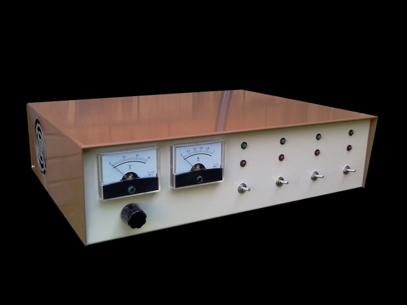
FM jammer: enclosure
(click on the image for a larger version)
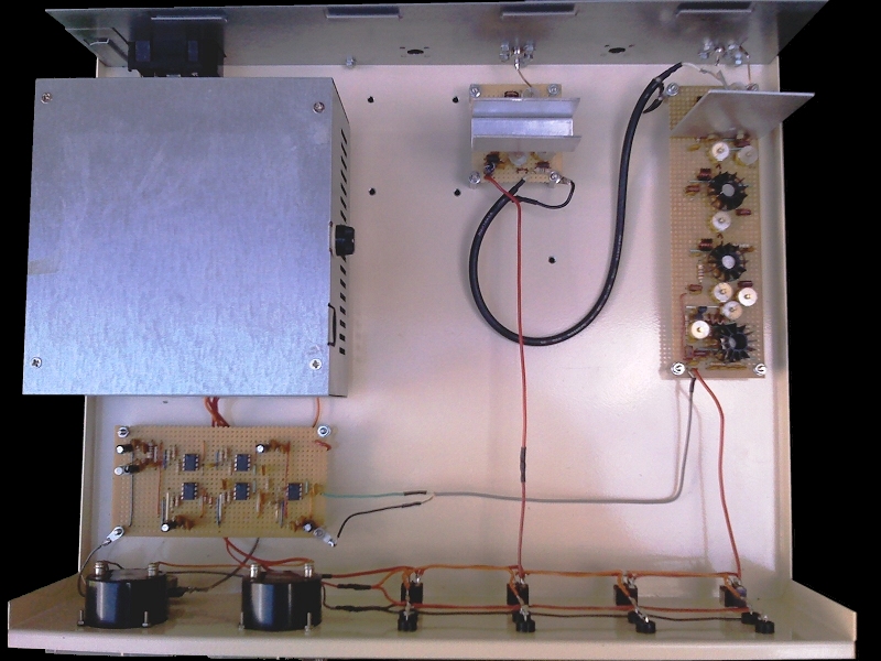
FM jammer: inside
(click on the image for a larger version)
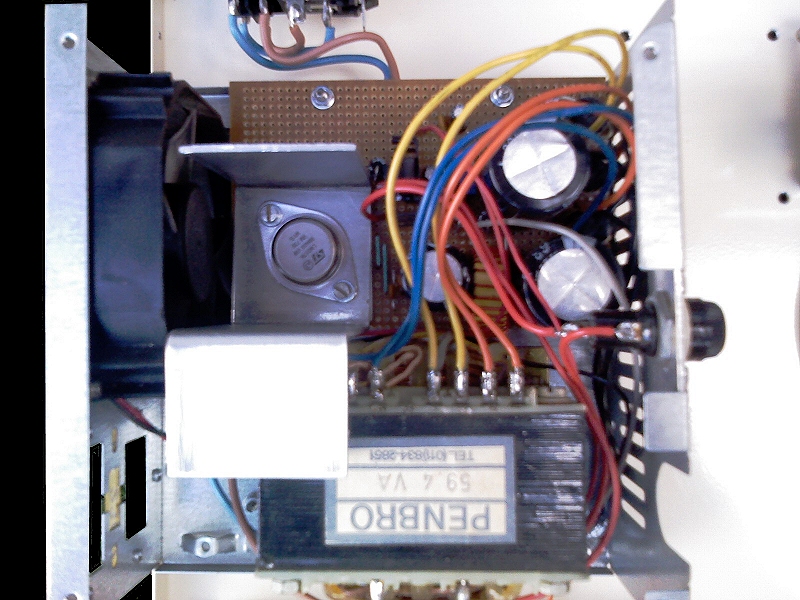
FM jammer: power supply
(click on the image for a larger version)
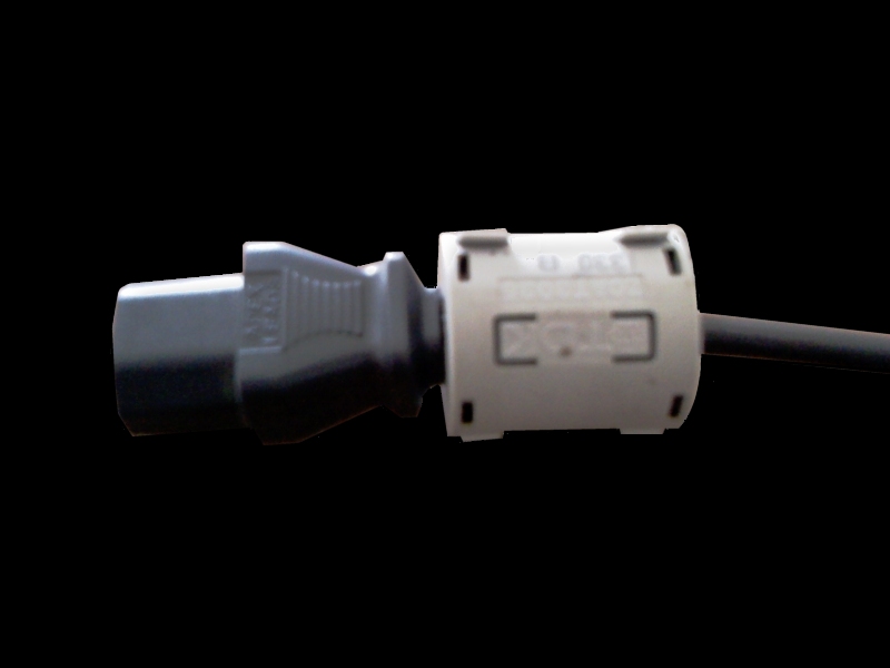
FM jammer: mains RF choke
(click on the image for a larger version)
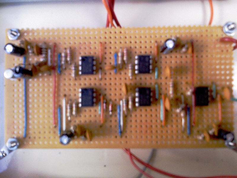
FM jammer: sawtooth and white-noise signal generator
(click on the image for a larger version)
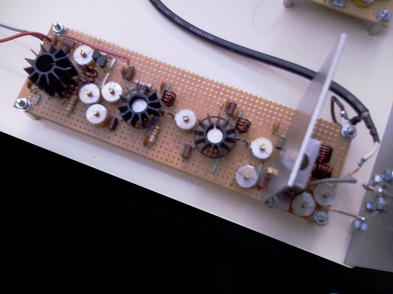
FM jammer: FM transmitter
(click on the image for a larger version)
Antenna's
 Contents and images
© 1998 to 2017 RaptorZone v8.0
All rights reserved